

Armoured cable or SWA (steel wired armoured) cable is the accepted standard for underground installations. This wire can be buried in the ground or can be fastened to exterior walls using cleats. The galvanised steel wire protects the wire from accidental damage caused by digging etc. Armoured cable comes in several different variables but for domestic wiring it will normally range from 2 core to 4 core. The conductor cores vary from 1.5mm for lighting circuits up to 16mm for heavy duty loads in domestic situations, some industrial SWA cable is much thicker.
The galvanised steel wire can be used as an additional earth and sometimes is used as the only earth, although this is not recommended.
When the armoured cable terminates at an appliance or junction box a gland is used. You must get the correct size and type of gland for the job at hand. If it is outside the gland must be waterproof. The gland serves two purposes, firstly it holds the wire and prevents it from being pulled out of the appliance and secondly it acts as a secondary earth.
| Before working on any electrical circuit you must ensure that it is isolated correctly and cannot accidentally be switched back on. Please read the article on safe isolation procedures before doing any electrical work. If you are not 100% certain what you are doing call a qualified electrician. Building regulations are changing all the time and modifying your home electrics could be against new rules and could invalidate your home insurance, if in doubt check first! |
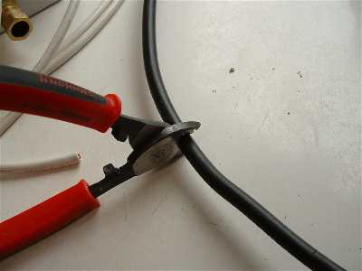
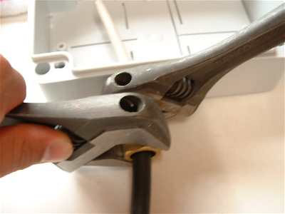
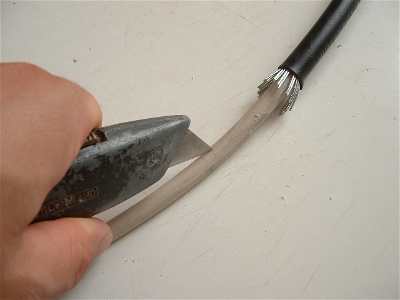
Armoured cable does not require any special tools, it can be cut with a pair of quality wire cutters like these in the picture or with a hacksaw. A pair of side cutters are useful for cutting the individual cores of the galvanised steel wire and two spanners of the correct size are needed for the effective fitting of glands.
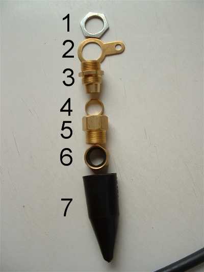
Below are the components for a external gland
1.Nut |
2.Earth Tag |
3.Nozzle |
4.Collar |
5.Collar nut |
6.Nut with rubber seal |
7.Cover |
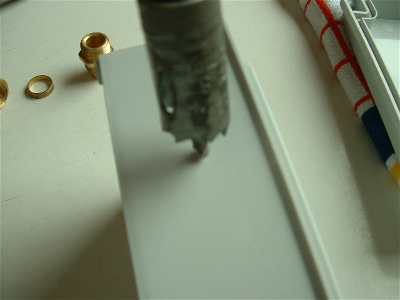
Here we are fastening two glands into a waterproof adaptable box for some external lights. Select a hole saw which is just large enough for the threaded part of the Nozzle to fit through and drill a hole in the box, do this on slow speed.
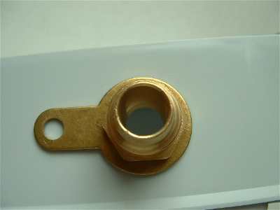
Push the threaded part of the Nozzle through the earth tag and then push this through the hole that you have just made. Screw the nut on the inside of the box to hold the nozzle in place.
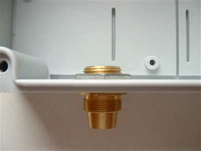
Use a spanner to hold one nut whilst turning the other nut with another spanner. Ensure that the nuts are tight, but do not over tighten them.
Now that the Nozzle of the gland is securely fastened to the adaptable box we need to prepare the cable. It makes sense to put the components on the cable before we start cutting it as the steel wire often makes it difficult to slide the components over. Cut the end off the protective cover and slide this onto the wire, make sure it is facing the correct way!
Next slide the Nut which contains the rubber sealing ring, the Nozzle nut and the collar onto the cable, this can now be pushed back far enough so that cutting the wire is easy.
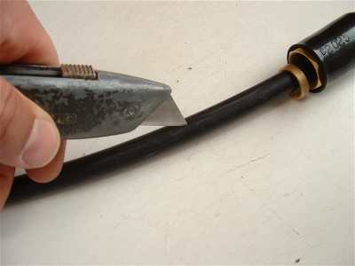
The outer protective sheath needs removing to expose the inner cable and the galvanised steel wire, simply slice this with a suitable knife and remove the protective sheath.
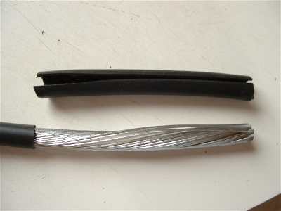
Here you can see that the outer insulation has been removed, exposing the galvanised steel wires.
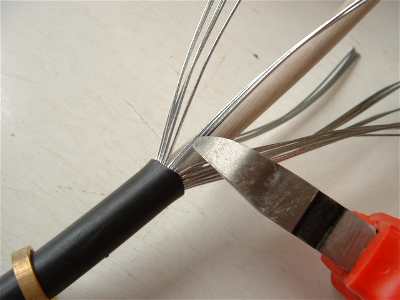
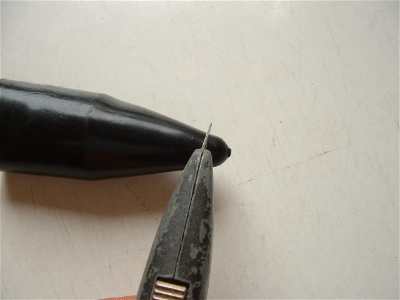
The individual steel wires now need cutting to a length so that they fit onto the nozzle which we fastened into the adaptable box earlier, I use side cutters for doing this, but many professional electricians use an hacksaw. If you use an hacksaw you can lightly score the steel wire and then bend it back and forth to break it off. Side cutters can only be used on this thin SWA cable because the end is squashed when cutting. If in doubt us the hack saw method.
The steel wires need flaring slightly and should look something like this. It is not easy to manipulate SWA cable, with practice this is probably easy but for the DIY enthusiast who only uses Armoured cable once in a blue moon it can be difficult.
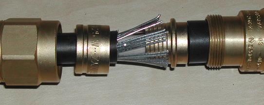
Push the wire so that the inner core goes through the Nozzle and then flare out the galvanised steel wires so that they are on the outside of the Nozzle. Now push the collar firmly over the wire, this should grip the wires and can be difficult to push on.
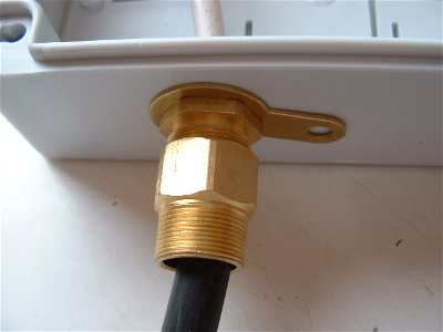
Slide up the collar nut and tighten it by holding the Nozzle with one spanner and the collar nut with another spanner, ideally this needs to be as tight as possible without stripping the threads.
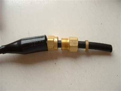
Now slide up the nut which contains the rubber seal and tighten this nut to the back of the Nozzle nut, again this must be tight and two spanners are needed. This nut has a rubber seal which grips the insulation on the cable, making a water tight seal.
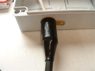
Slide the protective cover over the gland and you have successfully terminated a wire at an appliance/ box.

I mentioned earlier about glands being used for continuity of earth. Here you can see that I have drilled a hole through the plastic box which aligns with the hole in the earth tag. I have also marked a hole in the centre of where the second gland needs to be positioned, this way all we need to do is fasten a rustproof bolt through the hole and tighten it for continuity of earth. On the inside the bolt should be earthed to the existing earth wire by using a suitable crimp connector
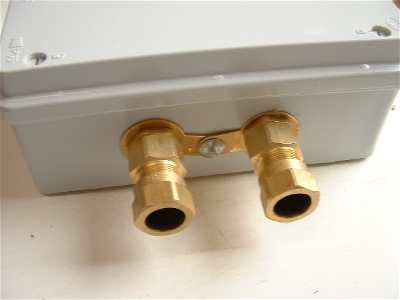
Both glands are fastened securely and have continuity of earth with the bolt that connects the two earth tags together. This bolt needs to be rustproof (preferably brass) and tight.
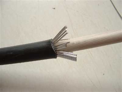
The inner insulation can now be removed from the cable, here I have removed it from the box for clarity. Using a sharp knife cut a slit down the centre of the wire but be careful not to go through completely as you do not want to damage the inner insulation on the individual cores. Remove the insulation to expose the cores of the cable.
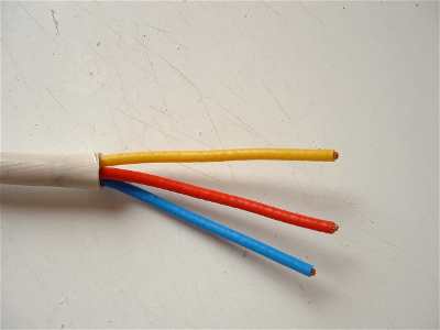
Here the cores are exposed and are ready to be stripped.
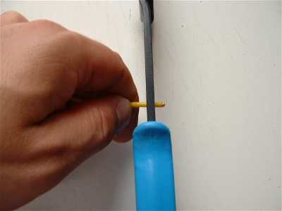
Now you can remove the insulation from the individual cores using a pair of wire strippers and then join the wires using suitable connectors.