

Lighting circuits in the home are normally protected by a 5 amp fuse or a 6 amp circuit breaker, there are normally 2 circuits one for upstairs and one for the ground floor. These lighting circuits are normally wired using 1.0mm2 twin core and earth cable, although 1.5mm2 twin core and earth is used in some cases where the lighting circuit is particularly large, it is possible for a lighting circuit wired with 1.5mm2 cable to be protected by a 15 amp fuse or 16 amp circuit breaker.
| Before working on any electrical circuit you must ensure that it is isolated correctly and cannot accidentally be switched back on. Please read the article on safe isolation procedures before doing any electrical work. If you are not 100% certain what you are doing call a qualified electrician. Building regulations are changing all the time and modifying your home electrics could be against new rules and could invalidate your home insurance, if in doubt check first! |
The maximum permissible load of a lighting circuit protected by a 5 amp fuse is 1200w or 12* 100 watt lamps
Every electrician has his or own way of wiring lighting circuits but basically there are only three different ways, two of these are almost identical.
Loop in at switch

This is what I consider the hard way, It is difficult because you do not have lots of room inside the switch box but has the advantage of having a neutral wire inside which could be useful for wall lights etc!

This shows what the loop in method at the switch looks like, you can see the neutral wires terminated into a terminal connector
here is a diagram of the connections at the switch with the earth removed for clarity.
As you can see from the above diagram the 3 Neutral wires are all connected together in a insulated terminal, the live in and out are connected together at the non switched side of the circuit and the switched live goes to the Lamp!
Loop in at ceiling rose
The loop in wiring system is straight forwards but has the disadvantage of making it difficult to replace the ceiling rose for a more modern style light fitting.
This diagram shows how the power is fed from the consumer unit to the first light and then to each consecutive light on the circuit hence it is named the circuit wire. The earth wires are not shown for clarity.
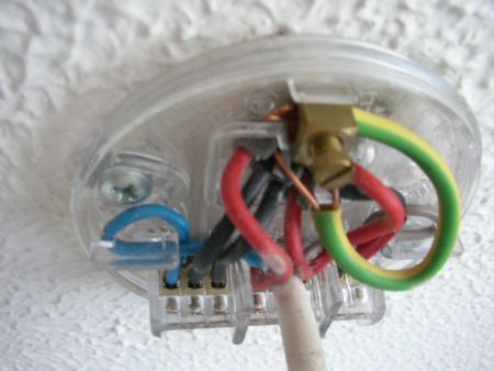
A typical ceiling rose would look like this with the cover removed

This is much simpler than it appears, for ease of explanation I have numbered the three terminals at the ceiling rose. The Electricity travels along the wire from either the consumer unit or another ceiling rose, the live is connected to terminal 2 and the neutral to terminal 3 as are the wires which go to feed the next ceiling rose. The red wire from the switch is connected to terminal 2 and the black wire from the switch is connected to terminal 1, this black wire is the switched live and requires red insulation tape to be neatly wrapped around it as once the switch is ON the wire becomes live. This makes terminal 1 the switched live terminal. The lamp is now simply connected between the neutral (terminal 3) and the switched live (terminal 1) When the switch is turned on or off it restores or cuts the switched live terminal and the light goes on or off accordingly.
Here you can see the connections to be made at the switch, once again the black conductor becomes live once the switch is in the ON position and therefore needs wrapping in red insulation tape.

This is a typical example of a lighting circuit as seen from the loft
Junction box wiring method

This is my favourite method of wiring Lighting circuits for a couple of reasons, firstly you can work above the junction box as you wire it but with the ceiling rose system you have to stretch from a ladder, secondly you only need to have one cable to connect to the light, so there's just one Neutral, one switched Live and a earth- simple. To use the junction box method all you need do is replace the ceiling rose with a Junction box but instead of doing it on the ceiling you do it above the ceiling. A cable is now joined to Neutral (terminal 3) and switched live (terminal 1) and earth. This cable is passed through the hole in the ceiling and wired directly to the light fitting, remember to put red tape around the black insulation as this is the switched live!

A typical lighting circuit junction box will look like this when the cover is removed
When a lighting system is installed in a property, the electrician normally wires it the easiest way which is to simply have the light fitting along side of a joist, the screw from the ceiling rose will hopefully get a grip in the beam or joist which will hopefully hold the light fitting up, the problem with this is when you wish to replace it with for instance a combination fan/light. Screwing into the joist whilst covering the hole in the ceiling made from the wires that have been pushed through is almost impossible!
You will also find in older houses that in the main living room the light is off central, this is because when the house was built a rack was placed over the fire for drying clothes and so the light had to be fitted off centre. Heavy light fittings require special care when fitting, if one drops from the ceiling it could be fatal!
The best way to support a heavy light fitting is to lift the floor boards above the ceiling rose unless you are in a upstairs room, in which case it should just be a matter of going into the loft space. Now locate the wires that are feeding the light fitting and after isolating the supply and marking the switch wires pull them into the area where the joist or beams are, now wire the circuit back up by following the instructions for the Junction box wiring system. Measure the distance between the joists or beams and cut a piece of 3/4 inch plywood or block board to the correct size, make the board approximately 12 inches wide. Place the board on top of the hole where the old light fitting was and then mark the hole from below. Drill the hole out and then cut 2 pieces of 2 inch by 1 inch timber 1 foot long. Screw the 2 pieces on the top edge of the board then screw the two pieces of 2*1 into the joists or beams. Now simply push the wire for the light fitting through the holes, then connect to the new light fitting and screw to the ceiling, switch the electricity back on and test!