G’d Evening Everyone
I am not an electrician and have never wired contactors before so at the risk of making a fool of myself in this my first post - even after having spent ages googling for info - I shall really appreciate if someone in the know can confirm whether or not what I am proposing to do is correct.
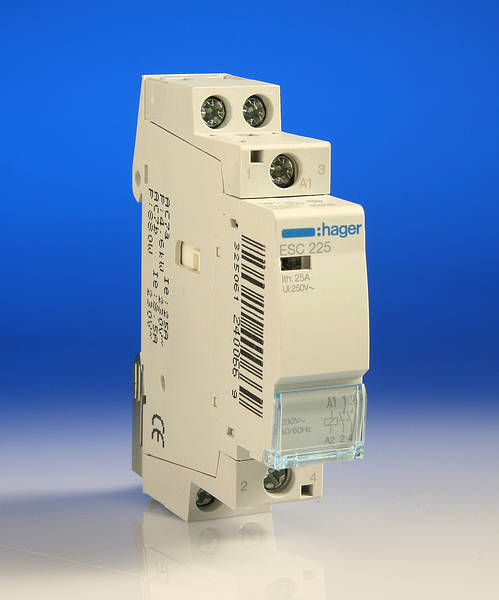
I am replacing the original 15 amp rated 1960’s thermostats which control electric under floor heating with Heatmiser thermostats Model PRT-E (13A resistive load, not the later 16A model which weren‘t available at the time when I bought them). Whilst most of the under floor heating circuits are about 2kW and can be connected directly to the thermostats, the lounge under floor heating circuit is 3.8kW and at 240V will exceed the thermostat’s 13A resistive load limit so it is for this circuit that I am planning to use a Hager ESC225 contactor module (situated in the attic in its own enclosure where hopefully it’ll not be heard).
I have a power supply coming from a 16A RCBO to the flush steel box in the lounge wall where I’m proposing to place the thermostat; in an adjacent flush metal box I have two cables which I plan to use between the contactors in the attic and the thermostat, one to extend the live and neutral from the under floor heating to the contactors, the other to receive the output from the thermostat to control the contactors. There is also a further power supply from a 16A RCBO to the contactors position in the attic.
So arriving at my question , can you please confirm that my wiring at the contactors should be:
Live/brown from thermostat to A1 (at top of contactor module), neutral/blue from thermostat to A2 (at bottom of contactor module) to energise the coil when thermostat wants the heating on.
Live/brown from consumer unit rcbo to terminal 1 (top of module)
Live/brown from under floor circuit to terminal 2 (bottom of module)
Neutral/blue from consumer unit rcbo to terminal 3 (top of module)
Neutral/blue from under floor heating circuit to terminal 4 (bottom of module).
And what should I do with the earths, connect them all up using a connection block and place in the enclosure?
Many thanks.
Rgds
Kelvin
CONTACTORS - wiring confirmation sought please
Moderator: Moderators
-
Someone-Else

- Senior Member
- Posts: 14155
- Joined: Sat Sep 01, 2012 6:03 pm
- Has thanked: 42 times
- Been thanked: 2484 times
Re: CONTACTORS - wiring confirmation sought please
Link to your proposed contactor would help. (Found one, but not sure if its the one you want to use)
Above are my opinions Below is my signature.
Would you hit a nail with a shoe because you don't have a hammer? of course not, then why work on anything electrical without a means of testing Click Here to buy a "tester" just because it works, does NOT mean it is safe.
 If gloom had a voice, it would be me.
 Click Here for a video how to add/change pictures
Inept people use the QUOTE BUTTON instead of the QUICK REPLY section
Would you hit a nail with a shoe because you don't have a hammer? of course not, then why work on anything electrical without a means of testing Click Here to buy a "tester" just because it works, does NOT mean it is safe.
Inept people use the QUOTE BUTTON instead of the QUICK REPLY section
-
ericmark

- Senior Member
- Posts: 4170
- Joined: Tue May 10, 2011 2:43 am
- Location: Mid Wales
- Has thanked: 113 times
- Been thanked: 774 times
Re: CONTACTORS - wiring confirmation sought please
The PDF listing does not give numbers but A1 and A2 are normally the coil so likely you are correct. Is it not marked on the side of the relay?
The use of LZ060 (heat dissipation inserts) between all contactors installed or between contactors and adjacent devices is required.
Hope you noted that.
The use of LZ060 (heat dissipation inserts) between all contactors installed or between contactors and adjacent devices is required.
Hope you noted that.
-
Pou Sto
- Newly registered Member
- Posts: 4
- Joined: Wed Nov 21, 2012 1:45 pm
- Has thanked: 0
- Been thanked: 0
Re: CONTACTORS - wiring confirmation sought please
the terminal numbers are just visible (when image clicked to enlarge)someone-else wrote:Link to your proposed contactor would help. (Found one, but not sure if its the one you want to use)
http://www.tlc-direct.co.uk/Images/Prod ... ESC225.JPG
-
Pou Sto
- Newly registered Member
- Posts: 4
- Joined: Wed Nov 21, 2012 1:45 pm
- Has thanked: 0
- Been thanked: 0
Re: CONTACTORS - wiring confirmation sought please
Thanks for the info. I am proposing to put the contactor module in its own 2 module enclosure in the attic, viz., there will NOT be any other module in it other than an adjacent blank so hopefully potential overheating will not be an issue. Yes, you are correct, there is a schematic diagram on the front but I am not an electrician and even on an electricians' forum I have noted disagreement as to its interpretation and whether the supply should enter the top or bottom! The terminal numbers appear to be the same whatever make of contactors are purchased with odd numbers at top and even numbers at bottom; it looks like that when the coil is activated terminal 1 will connect to terminal 2, terminal 3 to terminal 4.
the terminal numbers are just about visible here when the image is clicked to enlarge:
http://www.tlc-direct.co.uk/Images/Prod ... ESC225.JPG
the terminal numbers are just about visible here when the image is clicked to enlarge:
http://www.tlc-direct.co.uk/Images/Prod ... ESC225.JPG

-
Pou Sto
- Newly registered Member
- Posts: 4
- Joined: Wed Nov 21, 2012 1:45 pm
- Has thanked: 0
- Been thanked: 0
Re: CONTACTORS - wiring confirmation sought please
yes, I agree, that'd certainly have been a much easier and cheaper solution and I was prepared to go down that path but the advice from Heatmiser is that even with a 16A rated thermostat they recommend using contactors for loads as high as 3.8 kW because the current would be so close to the thermostat's 16A limit (15.83A at 240V, 16.17A at 235V).warmadmax wrote:wouldn't it be easier to return / ebay the 13A thermostat and buy the 16A one now they're avalible?